New to subsea navigation?
- Nortek Wiki
1. What is subsea navigation?
Navigation can be defined as the process or activity of accurately ascertaining one’s position and planning and following a route, whether on land, at sea or subsea.
The process of estimating subsea position has one key difference from terrestrial navigation: GNSS, or satellite navigation, does not function underwater. Other GNSS-denied environments exist on the water’s surface, and vehicles operating here also require alternative navigation sources. The tools and techniques used for subsea (and surface) navigation are rather diverse, and their complexity and cost vary depending on how much accuracy is required.
For those operating below the surface, navigation can look different depending on the application. For example, some people may only need to know where they are in relation to a reference point, some may just need to travel out to a point and come back to the starting point, while others may require an accurate geo-referenced position, with the ability to track a vehicle on a map at all times and over very long distances. The solution and the accuracy requirements depend on what you are doing.
1.1 Who uses subsea navigation?
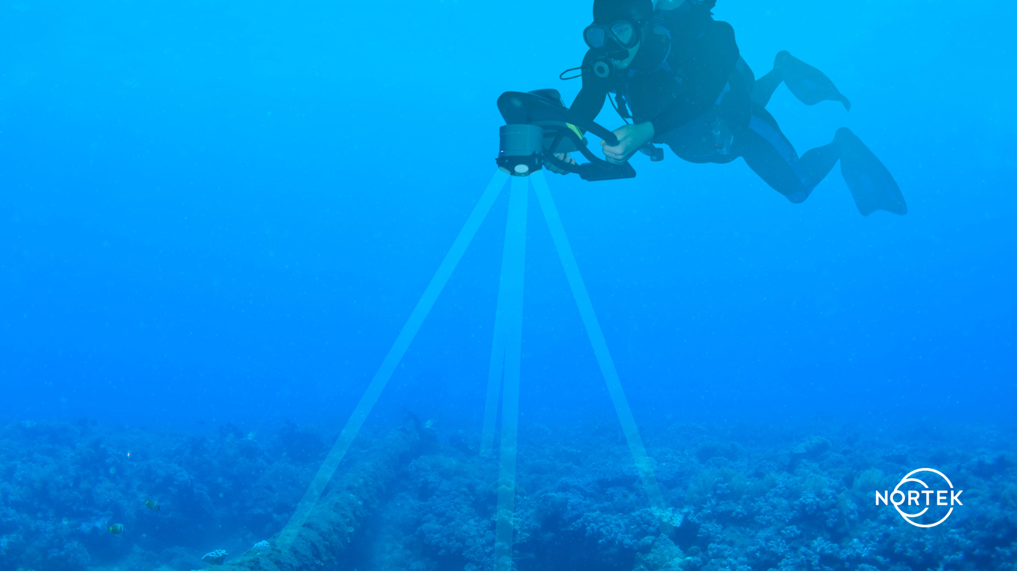
Applications requiring subsea navigation range from diver-held guidance systems for special-operations divers to large autonomous underwater vehicles conducting high-accuracy bottom surveys over large distances.
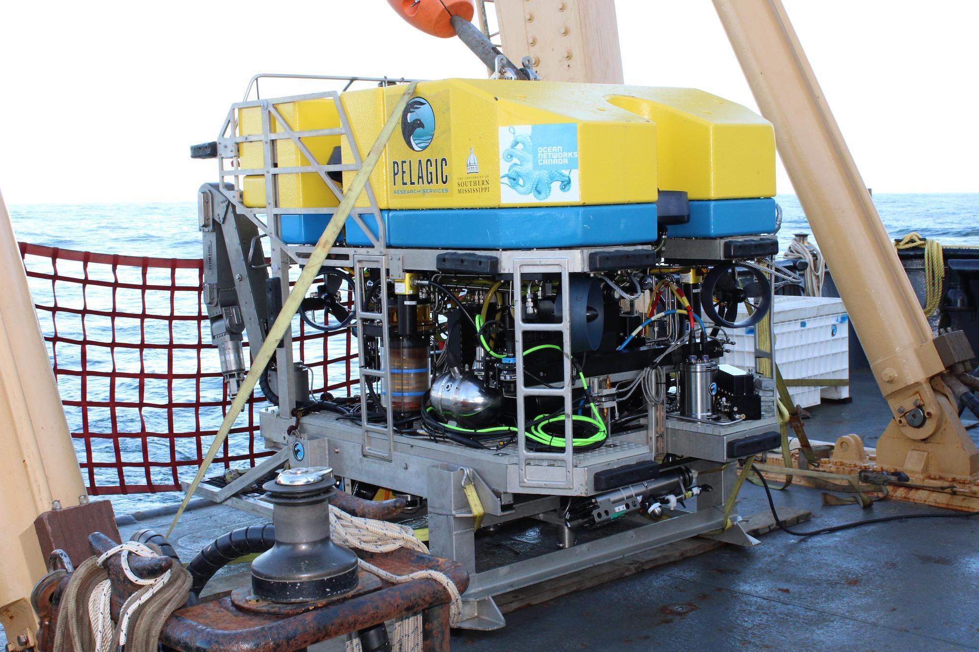
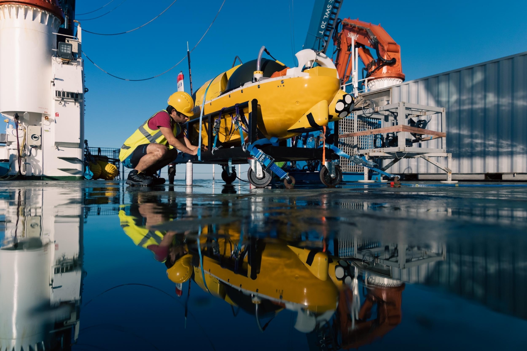
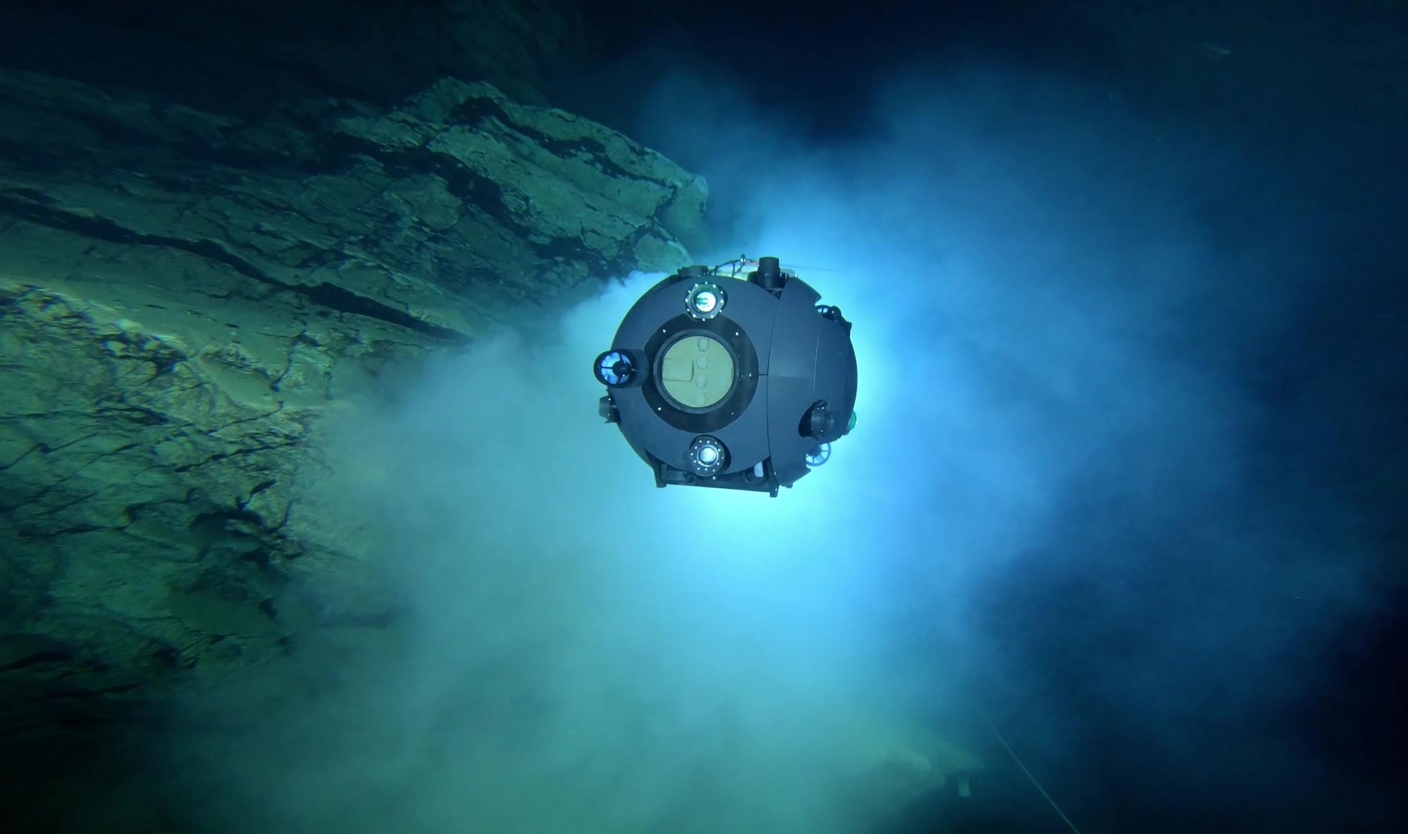
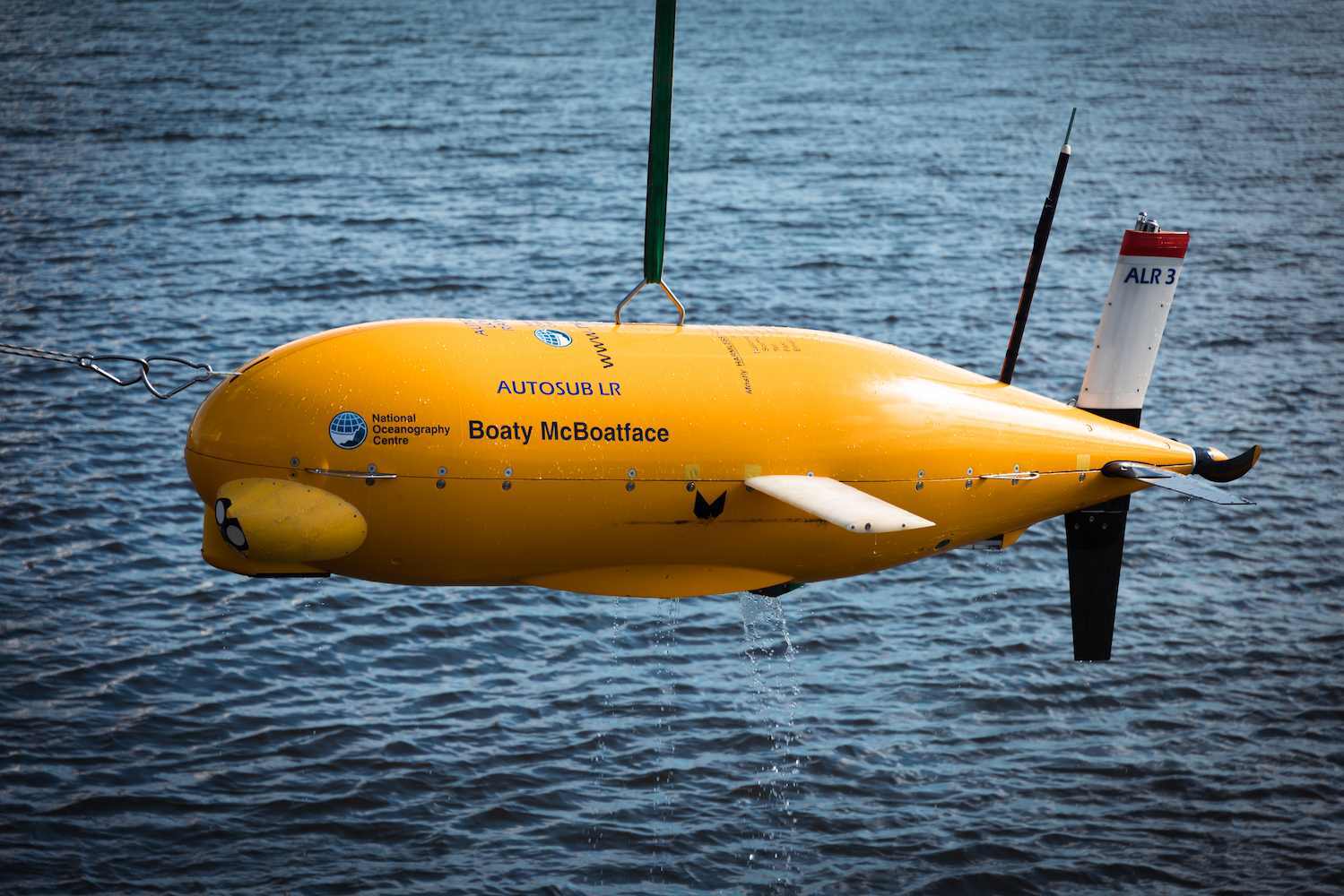
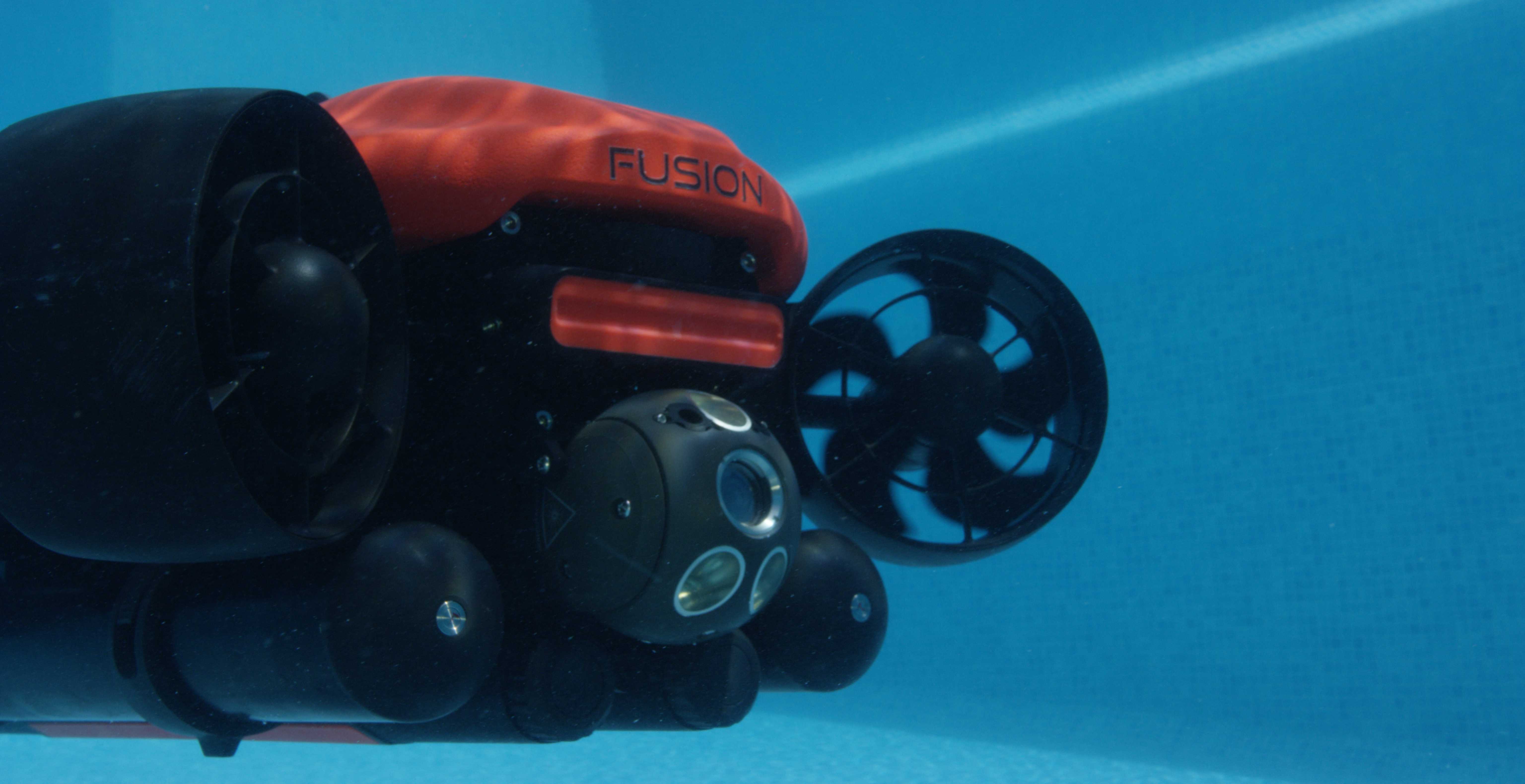
In more recent days, the dramatic increase of small and affordable Autonomous Underwater Vehicles (AUVs) and Remotely Operated Vehicles (ROVs) available on the market means more and more jobs can be performed by subsea vehicles. This can include collecting environmental data from other sensors such as conductivity, temperature and depth sensors, photographing and recording underwater phenomena such as hydrothermal vents, or using manipulator arms on a vehicle for subsea intervention.
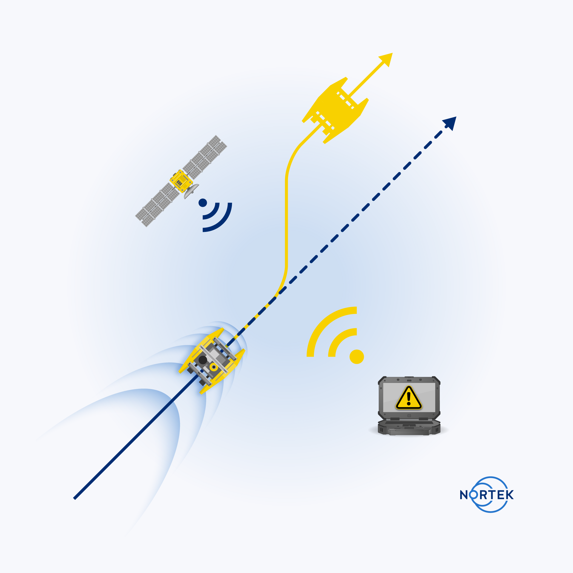
In addition to ROVs and AUVs, subsea navigation technology is increasingly being used in new environments and on new platforms. A key example is the Uncrewed Surface Vehicle (USV) sector, which typically relies primarily on GNSS for navigation. As USV technology commercializes, operators are looking for redundancy in navigation to protect against unplanned outages or degradation of GNSS positioning. These outages can occur from environmental factors, such as solar flares, or operating under infrastructure that can block GNSS reception, such as bridges. Another commonly discussed reason for GNSS outages is “jamming” or “spoofing”, in which the GNSS signal is interfered with intentionally. This is a common concern in military applications.
In cases where GNSS is lost, USVs will need a backup navigational sensor. A DVL can often fill this requirement and maintain vehicle position even in the absence of GNSS.
The challenge in creating a functional subsea navigation system is to strike a balance between the performance required for a given application (such as mission length, maximum allowed position error, environmental constraints etc.) and operational limits such as size, weight, power consumption and cost. This trade-off is common to any engineering problem, and different subsea navigation solutions are designed to best fit certain applications while adhering to these constraints.
A diver would want a light, low-cost solution, which also allows for stealth missions (missions that are hidden or not easily detectable. Small AUVs and ROVs may also require small, low-cost solutions, but may not need as high-accuracy data as divers would. Meanwhile, a long-range survey in a work-class ROV will require the greatest level of accuracy, which often comes at the greatest cost and largest size.
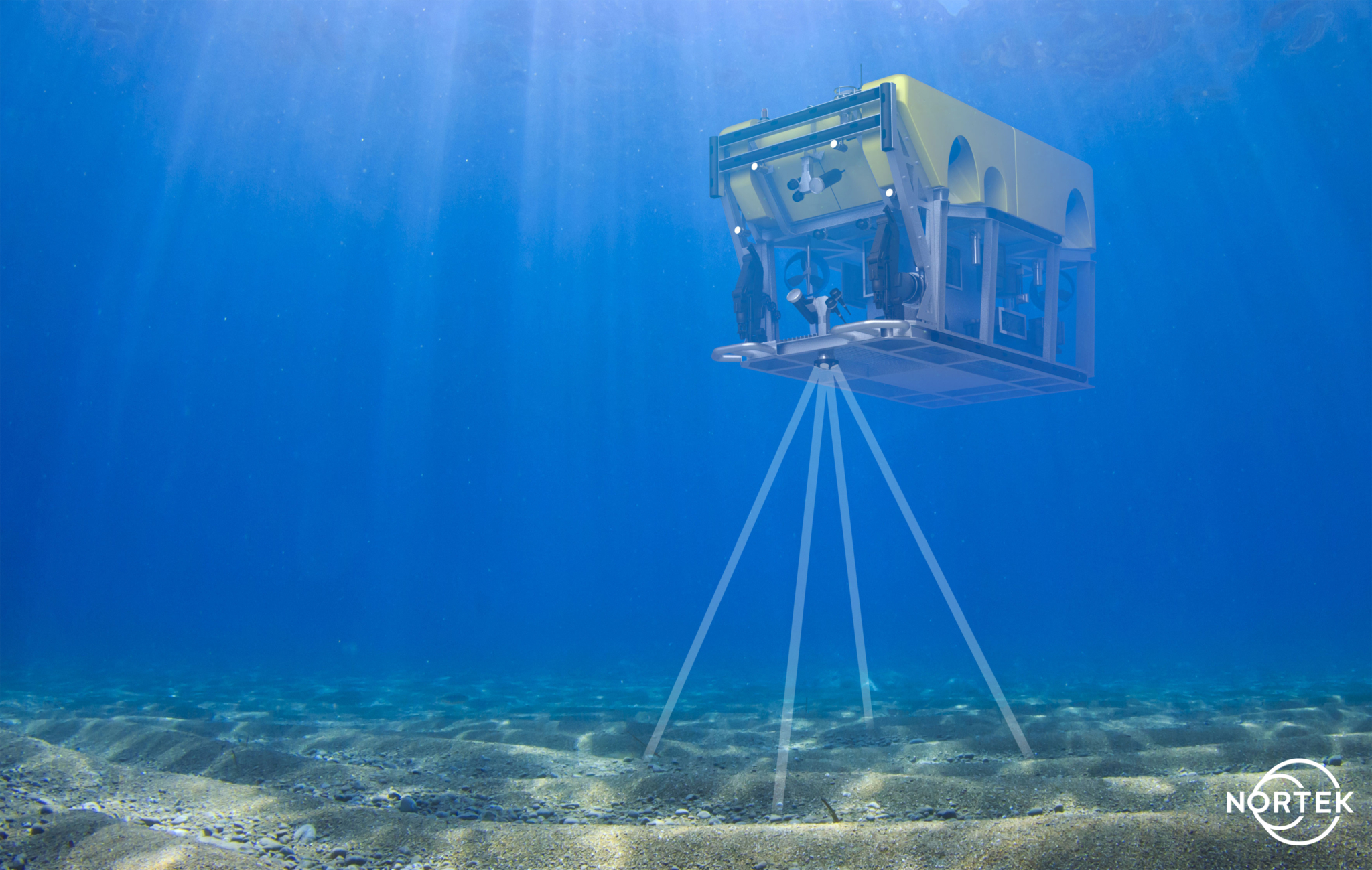
Finally, for any of these users, a DVL can be used for more than just subsea navigation. Many DVLs, including all of Nortek’s DVLs, can also perform current profiles, contributing not only to typical oceanographic data collection but also enhanced operational safety. In some advanced use cases, current profile information can be input into dynamic station-keeping algorithms as well.
1.2 The challenges of subsea navigation
The most obvious challenge with subsea navigation is that a continuously updated position fix must be estimated without a robust and dependable satellite reference (for example, a Global Navigation Satellite System (GNSS), including GPS, GLONASS or Galileo). There are several levels of autonomy that can be implemented in a navigation system, all of which come with their own set of challenges.
Not all uncrewed vehicles operate completely autonomously. Tethered remotely operated vehicles (ROVs) can be guided from the surface, where the operator (“man in the loop”) is located. The advantage of this approach is that the payload on the vehicle can be reduced, because navigation sensors need only provide basic functionality such as station keeping. However, the vehicle will need constant communication with a skilled ROV pilot.
On the other hand, if a vehicle is controlling and tracking its own position autonomously and without continuous communication with an operator, the navigation sensors and computers will all have to be mounted on the vehicle and relied upon completely. Autonomous behaviors can range from temporary station keeping during a GNSS outage, to completing a fully autonomous mission with no GNSS input, including navigating to and from a point of interest and avoiding obstacles along the way. A different sensor suite and different levels of accuracy will be required depending on the autonomous operations being performed.
However, even for tethered vehicles, there is a trend towards greater autonomy in the name of safety and cost-effectiveness offshore. In response, integrated navigation systems have improved accuracy, while reducing size, weight, power and cost (i.e. SWaP-C optimized) compared to a few years ago. Reducing the number of people controlling a system in the offshore environment creates greater reliance on navigational and operational data. More backups for sensors are required to enable autonomous vehicles to build in redundancy in their operations.
1.3 Subsea navigation: possible solutions
We find two classes of navigation system in common use. The first is based on acoustic positioning, and the second on the idea of integrating the output of motion sensors such as accelerometers, rotation sensors and velocity logs.
Acoustic positioning systems provide direct estimates of the position between points. In these systems, users can opt for a reference point located either on the surface with a GNSS position reference (in the case of USBL systems), or as part of a calibrated subsea array (in the case of LBL systems). In the example of a surface reference, the vehicle carries a subsea pinging source, known as the transponder. This transponder provides a range and angle to the surface listening node (called the transceiver) as it changes position.
These acoustic positioning systems come in two classes: Ultrashort Baseline (USBL) and Long Baseline (LBL).
1.3.1 Subsea navigation: Ultrashort Baseline systems (USBL)
USBL systems may not have the same level of accuracy as Long Baseline (LBL) systems (which we will discuss shortly), but they offer greater flexibility, reduced operational demands and continuous position estimates at the surface for vehicles below the surface.
These systems operate on the classic range-and-bearing principle in order to estimate position. Similar to LBL, they determine the distance (range) and angle (bearing) between a transponder and transceiver to determine the position of something beneath the surface. The level of accuracy for USBL depends on the expected errors of both the range and bearing estimates. The error for each of these is range dependent; that is, error increases as range increases. More sophisticated and expensive USBL systems have better performance, characterized by improved accuracy and greater range.
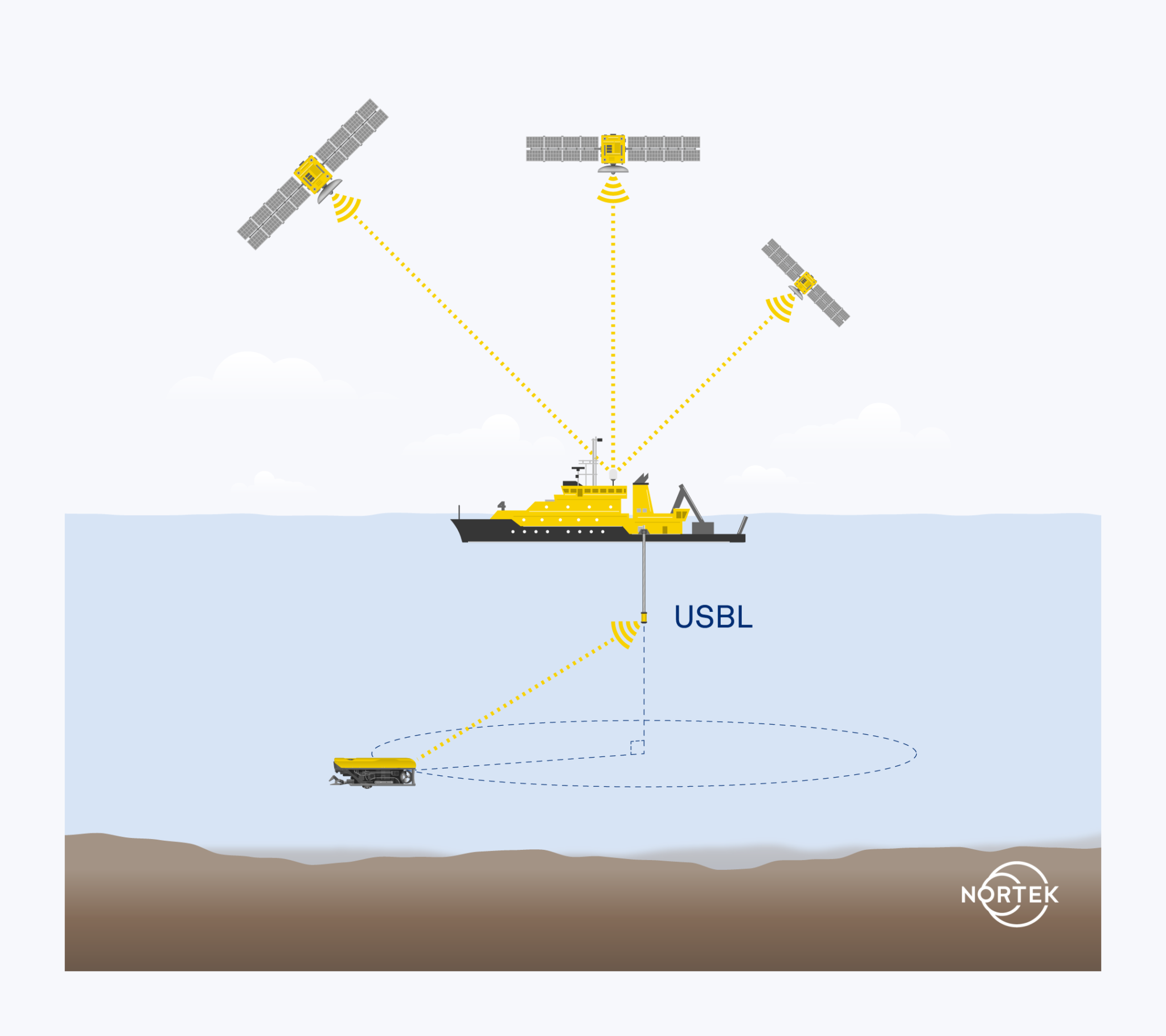
So, while USBL systems offer operators at the surface the ability to track their assets, they also provide a means for vehicles operating autonomously below the surface to get a position fix from the surface, where there is GNSS. This surface fix is useful for vehicles employing navigation solutions that accumulate error over time or distance. (Discover more about this in the section covering dead-reckoning navigation.)
The challenges for USBL are various, but perhaps the most important is handling the complexity of the path of travel.
Sound is transmitted over long distances along a path determined by the speed-of-sound profile of the water column and its boundaries. Non-uniform speed-of-sound profiles are always present, and when sound travels through a medium with different speeds of sound it will refract (in accordance with Snell’s law).
Exact knowledge of this profile is rarely known and therefore estimates of the angle to the transponder and the travel time will be modulated by this speed-of-sound profile. The error in the USBL’s estimates may be reduced with some knowledge of the sound profile, as well as by reducing the distance between the transceiver and transponder. The best estimates of position are achieved when the ping travels vertically through the water column.
Another important challenge to overcome with USBL systems is their inability to maintain stealth, which might be needed in, for example, military applications. Pingers employed in USBL to reveal a vehicle’s position are unlikely to be compatible with these applications, so it may not be possible to use a reference position at the surface (on a vessel).
USBL systems also need communicating devices not to be blocked from one another – there has to be line of sight, so that acoustic energy can travel between the USBL nodes. Another challenge arises in shallow water. When a transceiver receives a signal, it may also detect repeated copies resulting from multipath propagation (i.e. reverberation). This is common in shallow environments, where the ping is required to travel more horizontally than vertically. In fact, it is often very challenging to employ USBL in shallow water, and alternative solutions are often sought.
Copies of the ping will bounce off the bottom and surface boundaries, in addition to a straight path between the USBL nodes.
These copies may be distinguished from one another, but it is not always straightforward. This is particularly the case when the copies and the original overlap one another in time.
In summary, USBL is often a good entry into navigation and can also complement more sophisticated navigation solutions. But those considering low-cost USBL for small vehicles should prepare themselves for periods of loss of communications and/or degradation of position estimates in certain cases. In particular, USBL becomes challenging if the vehicle exposes itself to shallow-water multipath interference, which occurs when the horizontal distance is much greater than the total depth, or if the vehicle is traveling in and around structures that block and modify the ping path. Additional hardware and sensors must be relied upon for successful use of USBL, including GPS, heading sensors and other motion sensors.
1.3.2 Subsea navigation: Long Baseline systems (LBL)
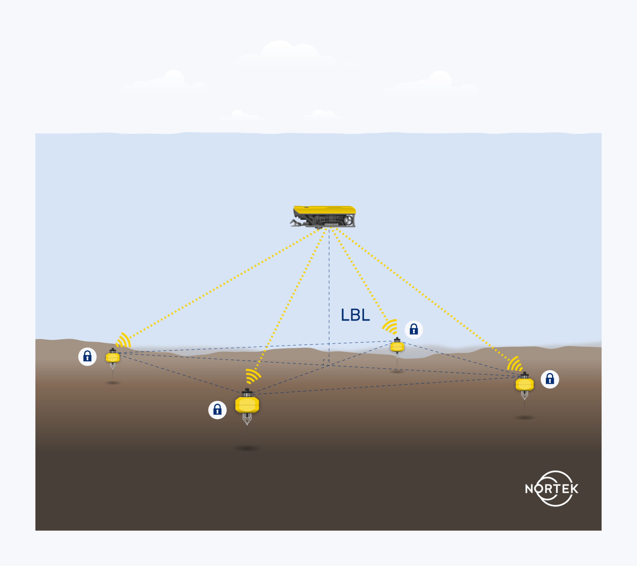
LBL uses networks of baseline transponders positioned on the seabed in fixed positions. The network of transponders typically surrounds the area of interest where subsea operations are occurring.
These positions are determined through a calibration process that requires references to a surface position. Once the positions of the transponders are known, then a vehicle or structure carrying a transceiver (listening node) may be triangulated upon to determine its position within the deployed network.
The accuracy of an LBL system is generally better than half a meter, but can be as fine as just a few centimeters. This depends on the size of the array and separation distance, along with how well external factors such as speed of sound are controlled, as we would expect in any triangulation positioning system. LBL systems can range anywhere from four transponders to over 150 covering a large area.
Ideally, LBL systems are used at locations where simultaneous operations require navigation, as it takes a long time to establish a calibrated array. Furthermore, the batteries of these LBL nodes need to be replaced periodically. Once an array is set up, however, multiple users can operate within the field and take advantage of the infrastructure.
Additionally, other sensors can be employed to increase the accuracy of the system. One crucial parameter with any acoustic positioning system is the speed of sound in water. Transponders with sound velocity sensors enabled can monitor speed of sound in real time throughout the array, ensuring high accuracy is maintained.
Overall, LBL systems are very accurate, but generally expensive to deploy and recover, as they absorb significant vessel time and require skilled operators to configure.
1.4 The role of dead-reckoning navigation in subsea navigation
Dead-reckoning navigation is the process of calculating an object’s current position by applying estimates of speed, time and direction since the object was at a previously determined position. It can be thought of as a step-by-step process: each estimate is based on the previously calculated position. When relying on dead reckoning for navigation, accurate instrumentation is crucial; once one estimate of position is off, all future position estimates will be even further from the desired course.
The change of position is the velocity multiplied by the time interval (e.g. if you travel at 90 km/h for one hour, you have traveled 90 km), and the direction of this change of position comes from the heading estimate.
Early mariners navigated by these means, though it was fraught with error, given that none of the individual component estimates were particularly accurate to start with – and combining them made things even worse. But if you were just trying to make it from one harbor to the next, then dead reckoning was generally considered fine.
It was not until dead-reckoning methods were employed in the subsea field that more attention was focused on the accuracy of the various components, or “sensors”, to reduce the overall position error.
1.4.1. Understanding heading and attitude in dead-reckoning navigation
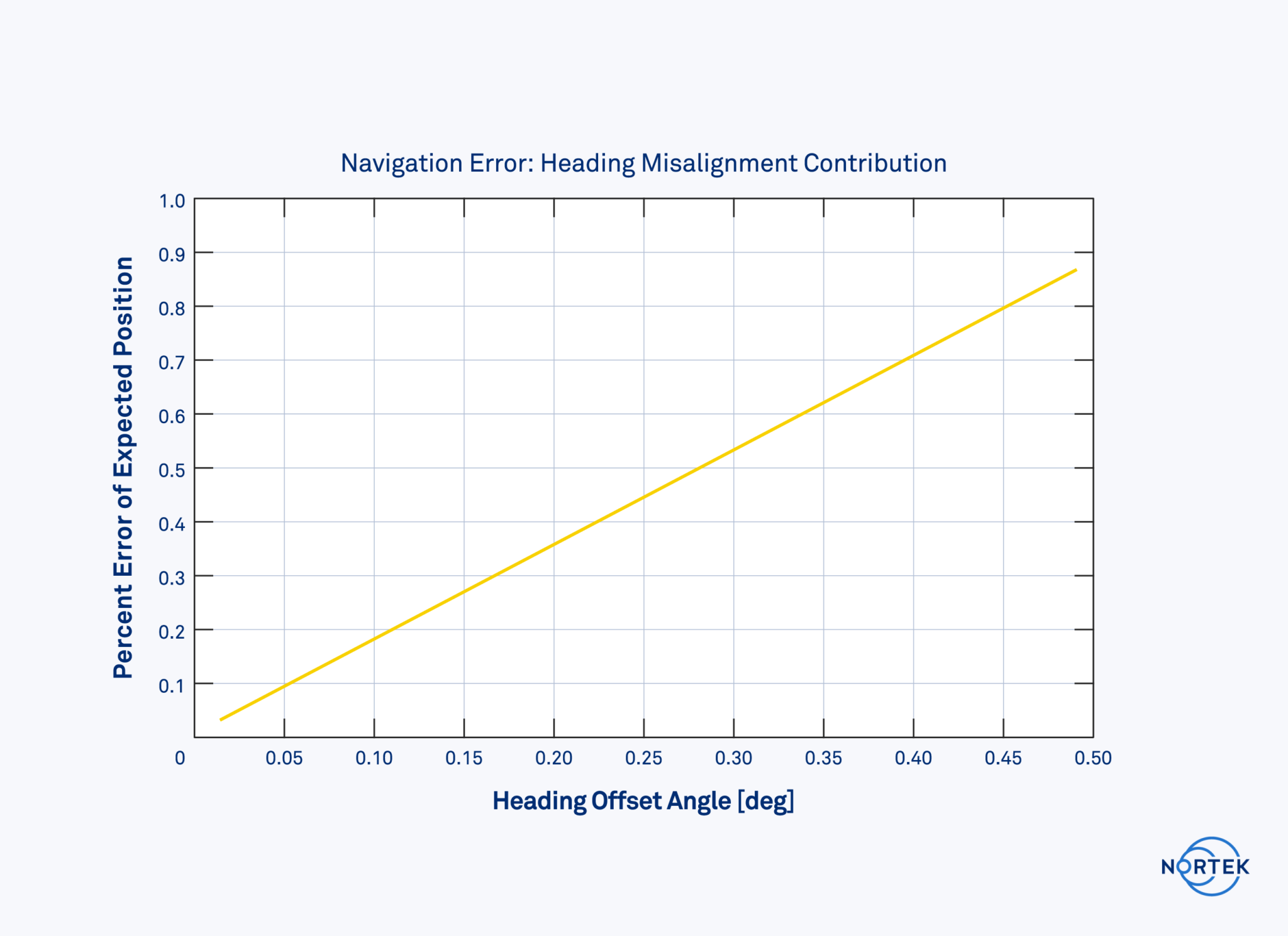
The heading sensor becomes particularly interesting for this form of navigation, because small errors in measurement can lead to large errors in position. For example, an error of 0.5 degrees in heading will result in an error of 8.7 m from the targeted location when traveling a straight course of 1 km.
This is the level of accuracy one can expect from a lower-cost, MEMS-based magnetometer type of heading sensor. It is also often acceptable for small vehicles with less demanding requirements. An old ship’s compass is the simplest form of a magnetometer heading sensor. In recent years, this principle has migrated across to miniaturized, electromechanical systems, otherwise knowns as MEMS.
Magnetometer-based heading sensors have the benefit of substantially smaller size and lower power consumption compared to higher-accuracy heading sensors. However, the accuracy is rarely better than 0.5 degrees. Furthermore, magnetometers are also sensitive to changes in the magnetic field, which may come from thrusters and power supplies on the vehicle itself. Ideally, they need to be calibrated to correct for fixed disturbances in the magnetic field. Disturbances in the magnetic field can also come from structures in the field of operation, such as pipelines and oilfield infrastructure, as well as natural sources such as diurnal variation and declination-induced changes depending on location.
Gyro-based heading sensors, also known as gyrocompasses, are an alternative, providing much better accuracy and freedom from reliance on the Earth’s magnetic field. But one must be prepared for the increase in price, size and power consumption.
These are sensor packages composed of three axial gyroscopes, which have exceptional sensitivity characteristics, sensing the Earth’s rotation and consequently identifying North accurately. These are called North-seeking gyros or gyrocompasses. Common North-seeking gyros that are used for subsea navigation are ring laser gyros (RLG) and fiber-optic gyros (FOG). Micro-electromechanical systems (MEMS) gyros lack the sensitivity to perform this task.
North-seeking gyros are generally impractical for smaller, low-cost vehicles, but are functionally mandatory for larger, more expensive Unmanned Underwater Vehicles (UUVs) on long missions or performing survey work.
An intermediate option is a North-keeping gyro. These sensors use the same principles as gyrocompasses, and are based on the same physical technology, but are not able to “seek” north themselves. Rather, they must be initialized with a heading. This makes them a good option for smaller vehicles that require non-magnetic heading capabilities but lack the space or budget for a North-seeking gyro.
1.5. Inertial navigation systems: IMU, AHRS and INS
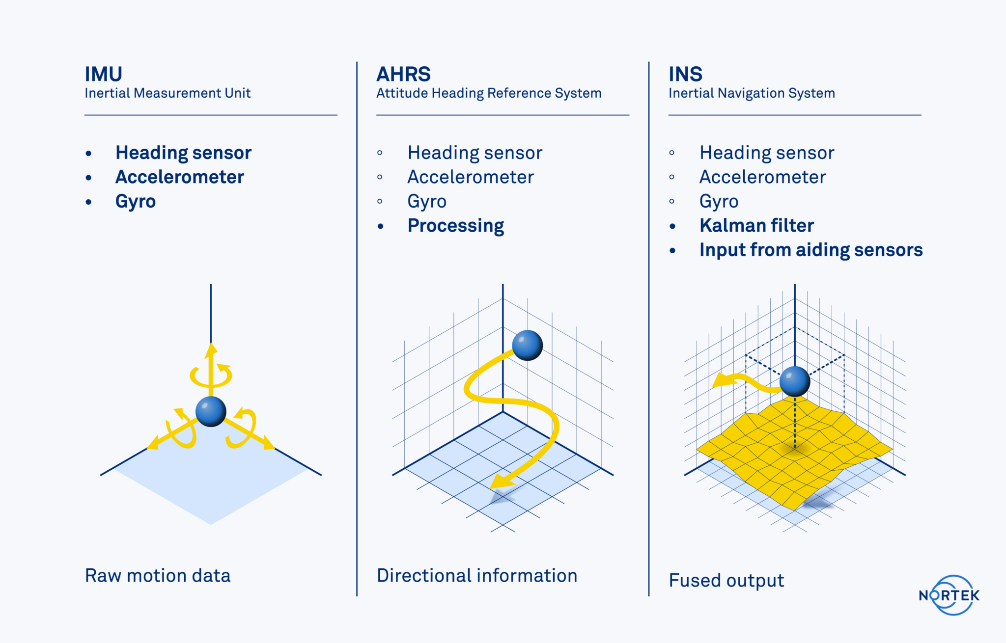
Dedicated sensor packages also include an IMU – a combined three-axis accelerometer and three-axis gyro – which makes for a complete inertial sensor package with six degrees of freedom. These by themselves may be referred to as Inertial Measurement Units (IMUs) and provide raw measurements of the axial acceleration and rate of rotation.
An IMU that includes processing to estimate heading and tilt can be described as an Attitude-Heading Reference System (AHRS). One may find AHRSs that include a magnetometer to estimate heading or alternatively a North-seeking gyro to estimate heading; the latter are commonly referred to as gyrocompasses.
An Inertial Navigation System (INS) is the next step in commercially available navigation sensor packages. This is essentially an AHRS with integrated algorithms and processing capability to estimate position, either as X/Y or lat/long coordinates. The standard approach is to employ a Kalman filter (see below) to fuse different data sources to estimate position.
IMUs, AHRSs and INSs rarely have physical differences between systems of the same “grade”; rather, the differences are in how the data are filtered and fused together.
One may consider using an inertial sensor package alone to perform dead-reckoning navigation, as it provides both heading and acceleration information; however, this is not sufficient. The challenge is transforming the inertial sensor’s estimates of acceleration to displacement. The acceleration from the inertial sensor must first be time integrated (multiplied by the time interval) to arrive at velocity with some slight error. This resulting velocity estimate must then be time integrated once again to arrive at the sought-after estimate of displacement.
This is a “double integration” process, which exposes the estimates of position to an error that grows quadratically with time. This rate of error growth, especially when combined with levels of drift associated with different grades of sensors in the package, means acceleration is not a very good parameter for estimating displacement of position, which is necessary for dead reckoning.
One may use accelerometers for short periods of time but after five, ten or 20 seconds, the error will grow beyond acceptable levels. These estimates are useful when there are data gaps in the velocity estimates, but do not offer a long-term solution. The bottom line is that the navigation solution requires a method of estimating displacement that does not drift excessively.
What an inertial navigation system requires is an estimate of velocity that does not drift and where there are no time-varying biases. This is where a Doppler Velocity Log comes in.
2. Doppler Velocity Logs and subsea navigation
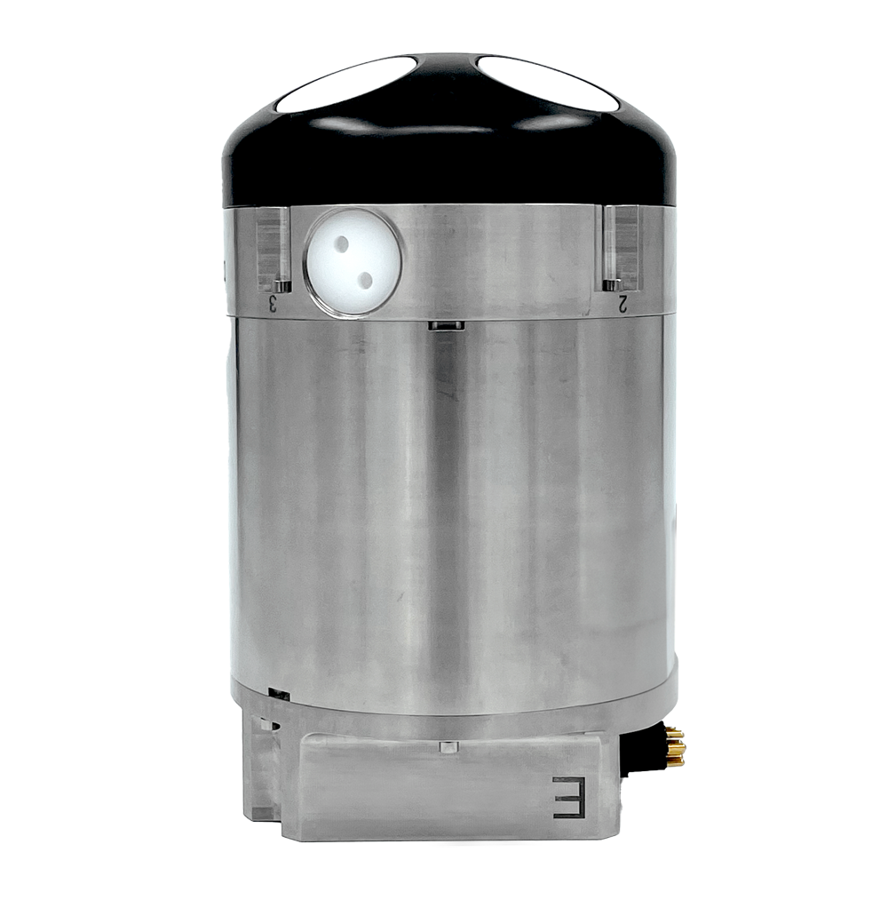
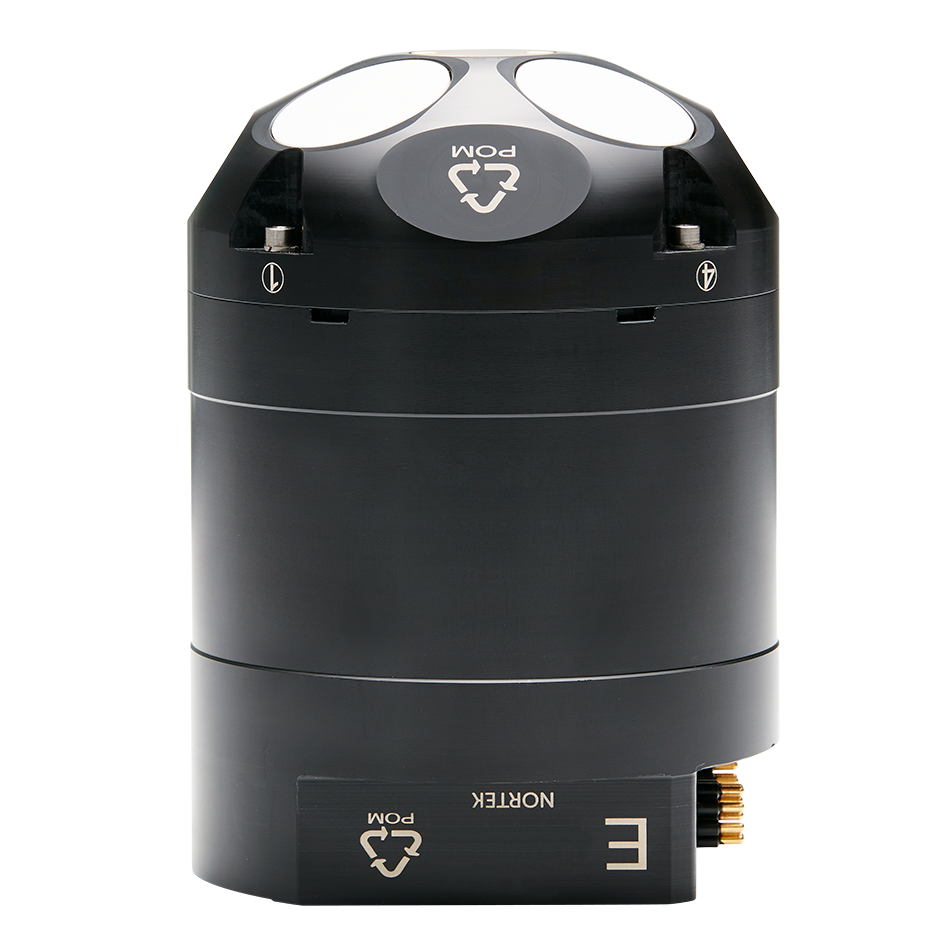
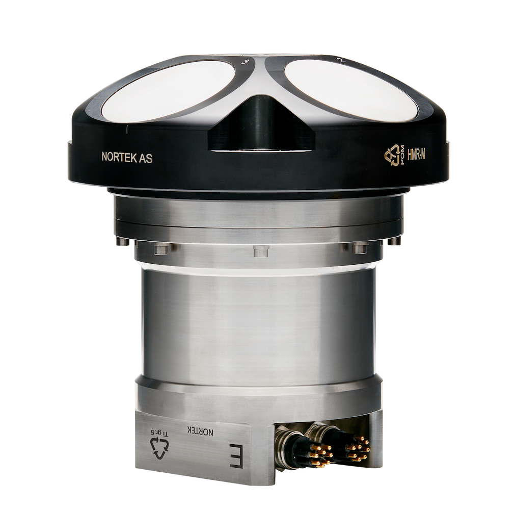
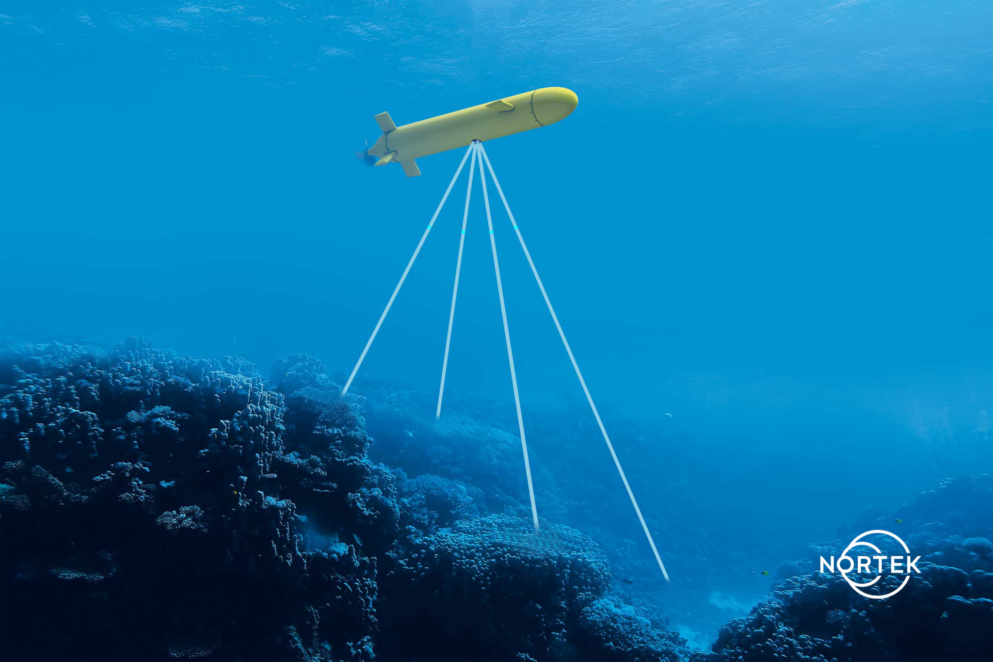
A Doppler Velocity Log (DVL) is an acoustic sensor that estimates velocity relative to the sea bottom. This is achieved by sending a long pulse along a minimum of three acoustic beams, each pointing in a different direction. Typically, this produces estimates of velocity converted into an XYZ coordinate frame of reference: the DVL’s frame of reference. Together with a heading estimate, these velocity estimates may be integrated over the ping interval (how long the DVL has been measuring) to estimate a step-by-step change of position, i.e. displacement = velocity × time step.
As mentioned with other inputs to dead-reckoning navigation, it is important to ensure that velocity estimates do not have any bias or offsets, because this will lead to a growing error in the position estimate. This is where the Doppler Velocity Log becomes a key part of subsea navigation: it offers an accurate estimate of velocity with zero-mean bias. All navigation solutions that are concerned about error growth must include a DVL, whether it is simply paired with a compass or part of a DVL-aided INS.
It should be noted that the DVL must be within range of the bottom to maintain bottom tracking. DVLs that have good range performance will naturally extend the operational altitude at which a vehicle can maintain accurate navigation, and therefore reduce the likelihood that a vehicle will have to rely on accelerometers alone to estimate velocity.
Range increases with lower frequency, but so does the physical size of the DVL (the transducers, specifically). This means there is a trade-off between DVL size and bottom-track range. When a DVL is not within range of the bottom, it may estimate the velocity relative to the surrounding water as an alternative; this is referred to as water track. Water track is less desirable than a bottom-track estimate, because the velocity is referenced to moving water rather than a fixed reference like the Earth’s sea bottom; currents are always present to some degree.
The value of a DVL can be measured in terms of its size, weight and power consumption, but its merits for navigation rest with its accuracy (usually referred to as Long-Term Accuracy – LTA – described as a percentage value of how accurately velocity is estimated) and with the complementing data products that allow for more sophisticated navigation. These other DVL data products, known as Time of Validity and Figure of Merit, are often integrated into the INS to bolster the reliability of velocity estimates.
2.1. DVL-aided INS
An Inertial Navigation System almost always employs a Kalman filter, which is a means of weighting multi-parameter inputs to estimate the error state of a system. In this case, we are referring to a navigation system, which may be a simple dead-reckoning system, or it may incorporate other inputs such as pressure, speed of sound and USBL.
The Kalman filter is too complex to explain fully in this article, but in essence it is an algorithm that uses a series of measurements observed over time, containing statistical noise and other inaccuracies. It uses these to produce estimates of unknown variables that tend to be more accurate than those based on a single measurement alone. This is done by using Bayesian inference and estimation of a joint probability distribution over the variables for each timeframe.
The algorithm works in a two-step process. In the prediction step, the Kalman filter produces estimates of the current state variables, along with their uncertainties. Once the outcome of the next measurement (inevitably corrupted with some amount of error, including random noise) is observed, these estimates are updated using a weighted average, with more weight being given to estimates with higher certainty. The algorithm is recursive. It can run in real time, using only the present input measurements and the previously calculated state and its uncertainty matrix; no additional past information is required.
2.2. DVL Time of Validity
A well-aided INS that employs a Kalman filter is concerned with two things in addition to velocity estimates. The first is ensuring that the estimates are synchronized in time. Errors can accumulate if the inertial and DVL estimates are delayed and can lead to error growth if care is not taken. Modern DVLs provide an estimate of the time when a DVL pulse is valid (or at the sea bottom). This will be unique for each beam. This is often referred to as precision timing or Time of Validity.
2.3. Understanding Figure of Merit in the context of subsea navigation
Following Time of Validity, the second data product that is particularly useful for improving navigation outputs is an estimate of the uncertainty of velocity estimates. An understanding of the uncertainty is important in subsea navigation because it helps to establish boundaries or confidence limits on the final estimate of position.
It is one thing to say: “I am at position X with a possible error of 2 m,” and an entirely different thing to say: “I am at position X with a possible error of 200 m.” One way to gauge the error is to use the uncertainty of the different inputs into the navigation solution. Even better, these uncertainties may be used directly in the Kalman filter to help establish the weighting and rejection of the different measurements. The result of this process is a more accurate estimate of position and a greater confidence in this estimate.
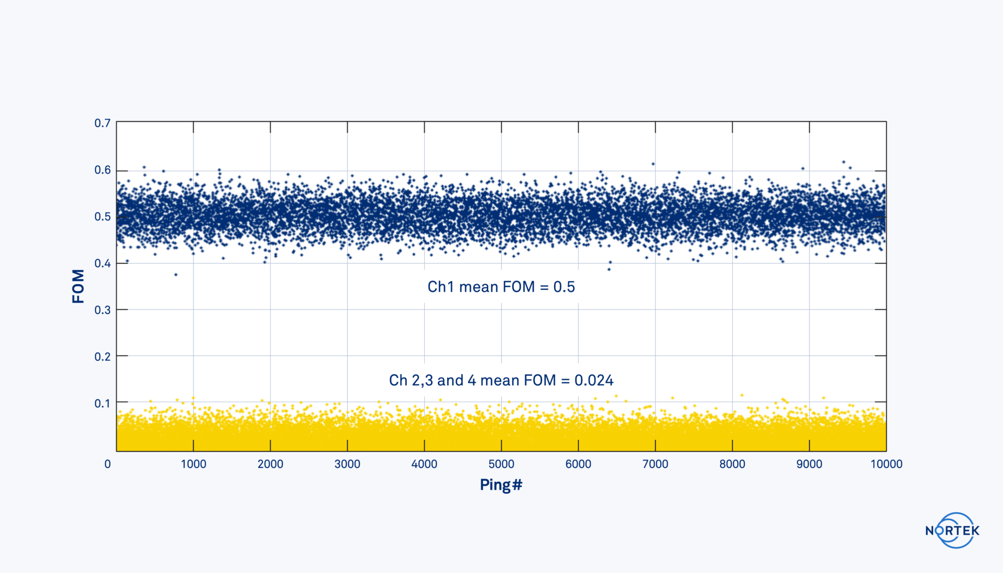
The estimate for a DVL’s velocity uncertainty is termed the Figure of Merit (FOM). It is unique for each pulse transmitted from each beam.
The Figure of Merit is different from error velocity. Error velocity is an indication that the internal measurements are in disagreement. The FOM is a measure of the confidence of the velocity estimates and is reported in terms of standard deviation. The FOM is estimated directly from the signal quality. This is important because it means that it can be estimated independently for each beam.
It is also worth noting that the FOM is not exclusively used by an INS. Simple dead-reckoning navigation may use the FOM to weight the individual beams. Additionally, the FOM may be used in a basic beam-rejection filter. Fish, mobilized bottoms from currents, external acoustic noise and complex bottoms that distort the returned signal are examples of sources that negatively affect the velocity estimates and can be quantified and remedied by the FOM.
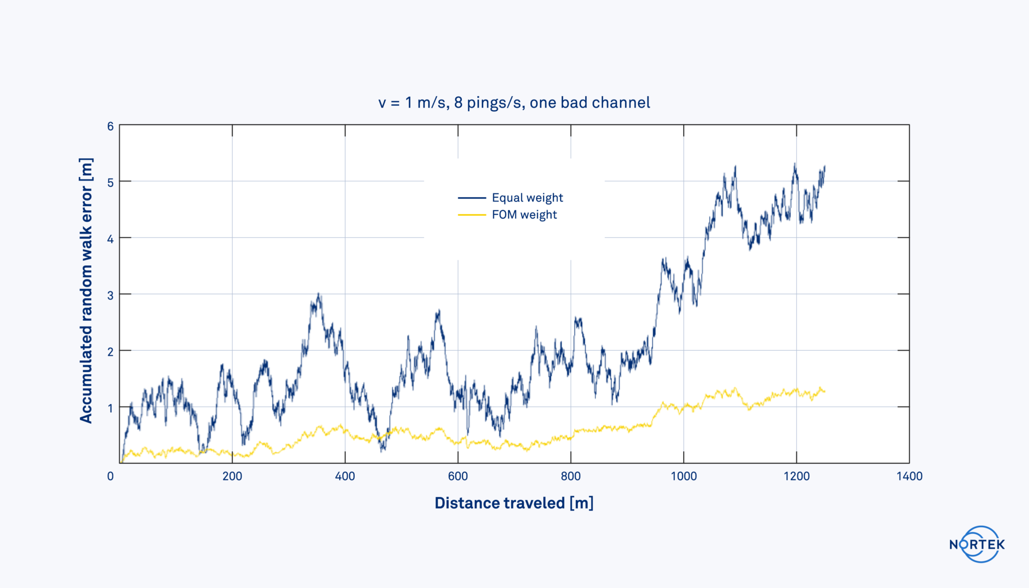
The plots below indicate how a single bad beam with a high FOM and noisy velocity estimates influences navigation accuracy (accumulated random walk error), with and without the weighting of the bad beam.
3. Error sources in subsea navigation
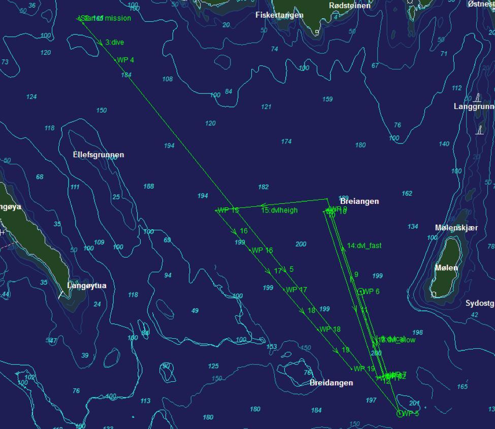
When considering error sources, it is useful to classify the types of error into three categories. These are (a) biases (static offsets), (b) random errors characterized by a mean-zero distribution and (c) transient errors. Of these, transient errors are the least manageable type, because they cannot be reduced by calibration or compensation.
Biases are fixed offsets, such as a misalignment between the DVL and heading sensor. As long as the error is static, it can be calibration corrected. These are the easiest to resolve.
Random errors, also referred to as random walk errors, are essentially the measurement uncertainty of the DVL (i.e. single-ping precision). Random errors may be reduced through averaging, because they have a zero-mean error relative to the true value. These types of error may also be reduced with a skilled INS and are errors for which the Kalman filter is inherently designed. The INS is also beneficial for these types of error, because the higher sampling rate of the inertial sensors can manage dynamic maneuvers; this is when random errors are not easily reduced though averaging.
Transient errors are the most troublesome because there is no straightforward means to correct them. Furthermore, the sources of these types of error are numerous; one example of transient error is seabed type, but many factors can cause these biases, which can come and go based on several conditions. The good thing is that these types of error do not become a concern until the accuracy requirements are below approximately 0.05 percent.
4. Calibration overview for subsea navigation
When pairing a DVL to a heading sensor or INS it is important to calibrate for (a) DVL-heading misalignment, (b) velocity scaling and (c) tilt offsets (primarily pitch). The process of calibration involves traveling along a straight line while the DVL, heading and tilt sensors collect data. This is often done at the surface, where it is easy to log a reference position (using high-accuracy GNSS).
The reference data allow one to determine the fixed offsets of heading misalignment, velocity scaling and tilt. Effectively the tracks drawn by GNSS references and by the DVL system should line up (DVL-heading misalignment) and the length should be the same (velocity scaling). A calibration conducted on the surface will have a zero vertical velocity; otherwise, there is a pitch offset. Though this process is challenging, once physically coupled and calibrated, in theory a DVL/INS recalibration is not required unless either the DVL or INS are decoupled from one another.
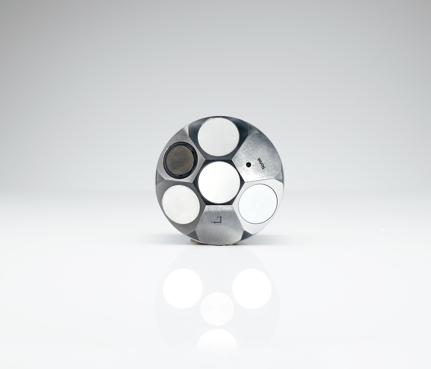
Some solutions exist where a DVL and INS (or other heading sensors) are mechanically combined and pre-calibrated. These all-in-one solutions reduce the integration time of a navigation system on a vehicle by removing the time and effort required for DVL and INS calibration. Regardless of whether a DVL and INS combination is provided in one mechanical solution, or simply coupled using an interface plate, a calibration is always required at some point in the production and commissioning process.
5. Conclusion: Choosing the appropriate navigation solution
Navigation of subsea vehicles and USVs can be a challenge, but the wide array of technology available on the market today means that for nearly every vehicle and every application, an appropriate navigation solution exists. At Nortek, we specialize in DVL technology, and high-performance subsea vehicles worldwide are equipped with our DVLs as part of their navigation system. As technologies to explore the depths of the Blue Planet continue to develop, the sensors that make subsea navigation possible will be increasingly important. We strive to keep up with the changing demands of this growing market, and hope you will trust us and our team with your subsea navigation endeavors.

